Posted by Armin on Thursday, January 06, 2011
I developed the camera trigger unit in order to synchronize various events and actions during free-flight experiments with hawkmoths in the wind tunnel described in a previous post. More specifically, the goal was to trigger multiple high-speed cameras and have LEDs that indicate the exact timing of electrical stimuli delivered via a miniature stimulus chip carried by a hawkmoth. (Electric stimulation of the moth is also triggered by the unit.)
The trigger is based on an Arduino micro-controller board (http://www.arduino.cc/) and provides a timed sequence of events after a trigger is elicited either manually, or automatically with the optional laser module. The latter is used to monitor a volume in space (the trigger volume) that, when occupied by an object (a moth, for example), elicits the trigger sequence. The module can be used with one or two red or infrared laser diodes. When using one laser beam, an object crossing anywhere along the beam will elicit a trigger event. When using two beams, the volume in space in which the two beams cross defines the trigger volume.


 occludes both beams by flying through their intersection, events are triggered.")
Timing of events
Phantom high-speed cameras (as well as many other high-speed camera models) are continuously recording image data into their internal buffer memory until a trigger event input is set high. To make sure a stimulus event is recorded by all cameras, a single "Trigger event" (red letters, top left) initiates the sequence illustrated in the figure above. The circuit immediately communicates with the transmitter for the chip on board the flying moth. From this time point on, it takes 84 ms until the on-board chip sends out its pre-programmed electric stimulus train (signal 1). Thus, another voltage output (2) is timed to coincide with the on-board stimulus to illuminate a set of LED indicators, at least one of which is visible in all cameras. This means that moth stimulation coincides with the onset of the LEDs.
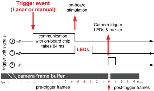
After a definable amount of post-stimulus time, a camera trigger signal (3) switches the "trigger event" input of the high-speed cameras. This stops the recording and leaves the last few seconds of video on the cameras' internal buffer. The settings on the camera determine how many post-trigger frames are saved, which in turn determines the maximum number of pre-trigger frames (npre) for a given memory size. In addition to the signals discussed in the above figure, the unit also produces an audible alarm when a trigger event occurs.
Arduino software
The main work of the circuit is performed by an Arduino (Diecimila) microcontroller board that I programmed in the Arduino programming language (similar to C). The microcontroller monitors several of its digital inputs to react when buttons are pressed, and to measure the light levels falling on two phototransistor-based sensors. It also performs the logic for sending out signals when certain conditions are met (e.g. button A is pressed, sensors A and B are below threshold, etc.).
The program is organized into three main loops, which correspond to different system states:
- Idle
- Armed
- Alignment
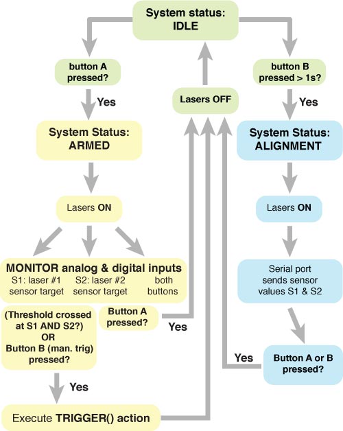
When the trigger unit is powered up, the program starts out in Idle mode, which is indicated by a green LED on the front panel. Pressing button A while in Idle mode leads the program to enter Armed status, in which lasers are turned on, and data acquisition on the two sensor channels is started. While in this loop (indicated by the red LED on the front panel) the microcontroller waits for both sensor levels to fall simultaneously, which happens when an object occupies the volume in which both beams cross. If this occurs, or button B is pressed as a manual trigger, the trigger function is called. This function leads to the timed sequence of events discussed above.
The Alignment mode is used during initial setup of the unit to help line up the laser beams with their respective sensor targets. The Alignment routine is initiated by pressing button B longer than one second during Idle mode. When in Alignment mode, both Idle and Armed indicator LEDs light up on the front panels, and both lasers are powered up. Additionally, the Arduino's USB serial communication is opened and sends the sensor values to a host computer at a Baud rate of 9600 bits/s. These values can easily be displayed with the serial monitor in the Arduino IDE. The goal is to maximize the light level (value of 1023) on each sensor by adjusting laser and sensor positions. Blocking the intersection of the laser beams with a mock target object leads to lower sensor readings. These lower readings should be noted and used as new threshold values in the code. After re-compiling and re-uploading the adjusted program via the USB connection, the laser trigger unit will be operational.
The laser trigger is optional and can easily be bypassed by a pull-up resistor between the 5V pin and the sensor inputs. This mimics a saturated sensor, and therefore the unit can only be triggered manually by pressing button B (labelled manual trigger).
Circuit description and diagram
Inputs to the microcontroller
 Laser trigger circuit diagram: Circuit diagram of the Arduino based laser trigger unit. Created in Eagle for Mac. Click to open in new window.
The heart of the circuit consists of the Arduino microprocessor which is indicated by the header pins on the left of the circuit schematic shown on the right (click to open in new window). Two of the analog inputs (0 and 1) are connected to the emitter sides of TEMT6000 ambient light sensors (Vishay Semiconductors, Shelton, CT), which act as laser targets. When light shines on these sensors, current runs from collector to emitter, so that the analog inputs are close to 5 V. In darkness, no current flows across the transistors, and the 10 KOhm resistors pull the inputs to ground. In a realistic situation, when an object blocks the laser beam impinging upon a sensor, the voltage will be somewhere in between 0 and 5 V, which gets encoded as a value between 0 and 1023 by the 10-bit analog converter. (The alignment routine described in section above helps find the correct threshold values.)
The momentary push buttons labeled "switch A" and "switch B", and connected to the microcontroller's digital inputs number 2 and 3 (see circuit diagram) are the main user interface with the trigger unit. Pressing these buttons allows switching between the functional states described above. Not shown in the circuit diagram are two BNC plugs that bypass these switches, so that a BNC cable with an attached switch can be used to trigger events from a certain distance to the unit.
Outputs from the microcontroller
The Arduino's outputs are used to power various LEDs as well as a small piezo-buzzer, indicating the current state of the program. Digital outputs also power the laser diodes, provides TTL logic signals, as well as switch the cameras and the radio transmitter via four optocouplers (4N25, Vishay Semiconductors, Shelton, CT). The following is a more detailed list of the outputs depicted in the schematic circuit diagram.
- Digital output 4 (labeled "Stim-TTL") is used to trigger the radio transmitter that communicates with the on-board stimulator chip. Depending on the position of switch S1, either a left (OUT1) or right (OUT2) button press on the transmitter is emulated. The connection to the transmitter is optocoupled (OK3 and OK4) to avoid contamination by the very high electrical noise present in the transmitter circuit.
- Digital output 5 is connected to a buzzer which indicates transitions between program modes with short beep sounds. It also produces a longer beep when a trigger event occurs.
- Digital output 6 provides a signal to an LED indicating trigger events
- Digital output 7 is for the LED indicatingIdle status
- Digital output 8 is for the LED indicating Armed status
- Digital output 10 provides power for the low-power laser diodes (Laser1 and Laser2). Both lasers can be run on the 20 mA an Arduino can deliver.
- Digital output 11 provides a 5 V TTL signal timed to coincide with the stimulus.
- Digital outputs 12 and 13 can be used to switch the high speed cameras. Both outputs are optocoupled to electrically isolate the circuit from the cameras. Output 12 is timed to coincide with a trigger event, output 13 is timed to coincide with the stimulus event occuring 84 ms later.
Camera Trigger Unit Arduino Code
The source code for the Arduino microprocessor can be found in a separate post: Arduino Source Code