Posted by Armin on Tuesday, January 04, 2011
Notes on the design and construction of a (relatively) cheap wind tunnel for the Daniel Lab.
I designed the Daniel Lab's wind tunnel as a virtual model in 3D CAD software (Google SketchUp: http://sketchup.google.com). Such a model was very useful for exploring and testing various design options before any actual structure was ever built. In addition, creating a parts list from the 1:1 model greatly simplified the ordering process. The wind tunnel design consists of three separable, but tightly attached, sections.
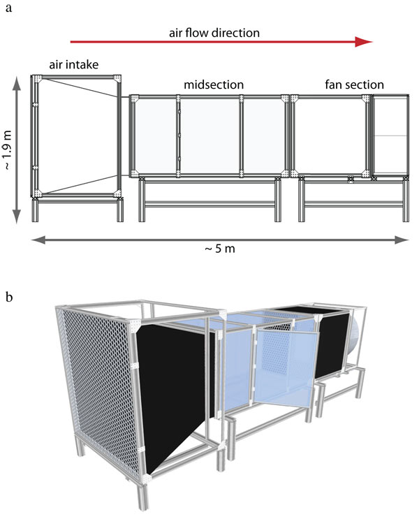
- Air intake: air enters the system through a 1.5 x 1.5 m air straightener consisting of aluminum honeycomb (1/4 in. honeycomb cell size, 2 in thick; HoneyCommCore. LLC, Cattaraugus, NY). The cross-sectional area of the wind tunnel constricts to 1 x 1 m over a distance of 1.2 m, at which point another air straightener is encountered.
- Midsection: this is the working area of the wind tunnel. The cross section is 1 x 1 m, and the length is about two meters, about 1 m of which is usable.
- Fan section: a large air circulator (Multifan TURBO36/120, Bloomington, IL), providing a maximum air throughput of $12,000 ft3/minute (ca. 5.7 m3/s) powers the wind tunnel. It is attached to a ca. 1 m long module with a honeycomb air straightener to buffer oscillations due to the revolving fan blades.
The structural skeleton of the wind tunnel consists of 80/20 extruded aluminum profiles (80/20 Inc.: http://www.8020.net/). The bottom support structure is constructed of heavy-duty 80/20 15-series profiles. It elevates and holds the upper frame of the actual wind tunnel, which is constructed of lighter 80/20 10-series profiles.
The walls of the mid-section, which have to allow an undistorted view of the inside, as well as IR and visible illumination from the outside, are of clear, high-quality acrylic sheets of 6 mm thickness. Sections that don't require a view of their inside volume are walled with black Sintra PVC, also 6mm thick. (Sintra is lightweight, yet rigid, expanded polyvinyl chloride (PVC) extrusion.)
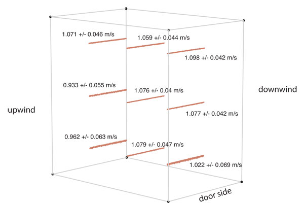
Wind speed measurements
The following image shows the wind speed measured at 9 different locations with an anemometer. The right side, looking upwind, experiences slightly lower velocities because of the proximity of a wall to the intake. The wind tunnel has just moved to a new room, where such wall effects will be far less important.
Assembled wind tunnel: images


Comments
Pulkit replied on Permalink
Research article
Hi Armin,
Thanks for the post. I was wondering if you know about any article or published research that uses this wind tunnel? Could you may be provide the title of such an article? I am interested in reading more about the tunnel.
Armin replied on Permalink
Papers
Pulkit replied on Permalink
Thanks Armin for the
Thanks Armin for the information. I am interested in knowing the turbulence levels in the wind tunnel. However, I couldn't find such information in the research articles using this (or a similar) wind tunnel. Do you know, may be, the approximate turbulence levels that exist in these kind of tunnels or a source where I can find such information? Also, if I understand the last figure on this webpage correctly, it shows the variation within upstream and downstream rather than at individual points, isn't it? I really appreciate you taking time to answer my questions!
Armin replied on Permalink
turbulence
Pulkit replied on Permalink
Turbulence
This already then provides information about the turbulence levels (assuming, of course, sampling rate was adequate) as the variation in the last figure is with time and not in space. Thanks for clearing that up!
Armin replied on Permalink
No problem...
Phil replied on Permalink
Honeycomb Attachment
Hello Armin,
currently i design a open blower wind tunnel by myself and i would like to know
how did you attach the honeycomb core to the aluminium frame?
Do you have any detailed pictures of the attachement?
Regards,
Phil
Armin replied on Permalink
Re: honeycomb attachment
Phil replied on Permalink
Hey Armin, thanks for your
Hey Armin, thanks for your response and your effort!